Internal forces diagrams for the two-support beam
The calculator draws the shear force and bending moment diagrams for a simply supported beam under various loads.
This online calculator shows internal forces diagrams for the simple (two-support) beam, pinned at one end and roller supported at the other, under a loading system. The calculator graphically depicts the bending moment M and the shear force Q acting along the bar. Plotting is necessary to determine the position of the most loaded (dangerous) section of the beam.
The theory and calculation formulas are below the calculator.
Just enter the loading system data in the table below and get the free-body diagram, shear force, and bending moment diagrams.
Load
| Distance to the support A | Load | Value | Direction | Moment direction | Range | Difference | ||
|---|---|---|---|---|---|---|---|---|
Internal forces
The following picture illustrates internal forces in a beam under loads.
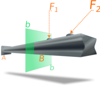
To determine internal forces at point B we pass an imaginary section perpendicular to the axis x along the axes y and z.
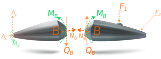
The free-body diagram of the beam section exposes internal forces acting at point B as external ones. The force component NB, acting along the axis x, is named the normal force. We skip normal force component calculation in the calculator since it allows only loads that act perpendicular to the beam.
The internal force component QB, acting parallel to the cross-section is termed as the shear force. The calculator gets only the y component of the sear force because the z component is equal to zero for perpendicular loads.
The couple moment MB is referred to as the bending moment.
The bending moment equals the sum of all the force moments applied to the beam segment relative to the center of gravity of the section.
The force components prevent the relative translation between the two segments, and the couple moment prevents the relative rotation. 1
Internal forces diagrams by integration.
We will find formulas for calculating the values of the shear force Q (x) and the bending moment M (x) separately for different segments of the beam.
The boundaries of the segments have prominent points: beam ends, support places, concentrated forces and concentrated moments applying points, distributed loads boundaries.
For each segment, the integral of the distributed load function q (x) is calculated to determine the shear force Q (x). The next step is to calculate the integral of Q (x) to determine the bending moment function M (x) in accordance with the formulas:
The distributed load q (x) in our calculator can be linear, linearly decreasing, or increasing. In the first case, q (x) is a constant, in the second, a linear function: q (x) = kx + b. In the absence of distributed loads in the section, the shear force will be constant.
Thus, to find the functions Q (x) as well as M (x), it will be necessary to get the indefinite integral of the polynomial and calculate the integration constant. The integration constant can be easily found if we know some point through which the required function passes. See: Polynomial integral.
As such a point, we will take the values of Q (x) and M (x) along the left boundary of each segment.
Q (x l ) will be equal to the shear force function value for the previous segment at the segment rightmost point plus the magnitude of the concentrated force (or support reaction) at this point if any. If the force acts upward, then the Q (x) alteration is positive, or negative otherwise.
M (x l ) will be equal to the value of the bending moment function M (x) for the previous segment at its rightmost point shifted by the value of the concentrated moment applied to this point if any. If the concentrated moment is directed clockwise, then the shift is positive, otherwise, it is negative.
The value of Q (x) at the left edge of the beam will correspond to the sum of the concentrated forces and the support reaction at this point or will be equal to zero if there are none. The value of M (x) at the ends of the beam is equal to the sum of the values of the concentrated moments applied to the ends of the beam. If there are no concentrated moments at these points, then M (x) will be equal to zero.
The signs for M (x) and Q (x) can be associated with the nature of the deformation of the beam under the action of external forces. If the bending moment in the section is positive, then the beam in this section bends with a bulge downward, if it is negative, then the beam bends with a bulge upward.
Example
Let's consider Q(x) and M(x) calculation by example:

- Firstly, find support reaction. You may see, how to do that on this page.
Calculated support reactions:
- Split beam in segments by key points: 0, 2, 4, 5, 6.
Segment А - boundary points: 0,2
Segment B - boundary points: 2,4
Segment C - boundary points: 4,5
Segment D - boundary points: 5,6 - For each segment:
- find distributed load formula q(x)
- integrate it to obtain shear force Q(x) formula.
- integrate again to get bending moment M(x) formula.
Integration constants are calculated by the left border coordinate of the segment using the formulas for the previous segment
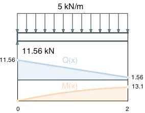
Segment А, boundary values Segment A
Distributed load is equal to: q(x) = 5. Integrate q(x) to find shear force:
Find integration constant C = Q(x)+5x, at the point x=0. Normally, shear force on the beam ents is zero, but on the left ent it is changed by support reaction VA=11.56kN, which directed upward. So, shear force in point 0 equals to: Q(0) = 0 + 11.56 = 11.56.
Hence C = 11.56 - 5 ⋅ 0 = 11.56
Shear force for segment А:
Integrate shear force function Q(x) to obtain bending moment formula:
We have no concentrated moments at point 0, so M(0) = 0.
Substituting x = 0 and M (0) = 0 in the expression for C = M (x) + 2.5x 2 - 11.56x = 0 + 2.5 · 0 2 - 11.56 0 we get the value C = 0
Bending moment for segment A:
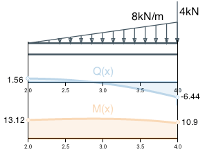
Segment B
To find the distributed load function q(x) we use line equation from two points.
By the points (2;0) and (4;8) we can find this equation: q(x) = 4x-8.
Integrate this function to find shear force formula.
By previous segment Q(x) formula calculate Q on the left boundary: Q(2)=-5∙2+11.56 = 1.56. Similarly to the previous segment, find the integral and integration constant by the point (2;1.56).
Segment B shear force formula:
see calculation
Find moment value at the point x=2 by the previous segment M(x) formula : M(2) = -2.5 ∙ 22 + 11.56 ∙ 2 + 0= 13.12 .
Integrating Q(x) and calculating the integration constant by the left boundary value get the bending moment formula for the segment B:
see calculation
Segment C
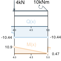
Calculate shear force at the point 4 by the segment B shear force Q(x) formula: Q(4) = -2 ∙ 42 + 8 ∙ 4 – 6.44 = -6.44.
The concentrated force F1=4kN abruptly change Q(x) value at the point x=4. It is directed downward, hence the addition is negative: Q(4) = -6.44 - 4 = -10.44
There is no distributed load on this segment, so the shear force is constant.
Segment C shear force formula:
The bending moment value at point x=4 is calculated by the formula M (x) for the previous segment: M(4) = -0.67 ∙ 43 + 4 ∙ 42 – 6.44 ∙ 4 + 15.33 = 10.91
Integrate Q(x) and calculate C by the boundary value get the segment С bending moment formula:
see calculation
Segment D
Since there is no distributed load, the shear force is constant along this segment.
Segment D shear force:
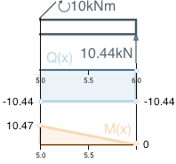
Calculate boundary value M(5) by the previous M(x) formula : M(5) = -10.44 ∙ 5 + 52.67 = 0.47
The concentrated moment M1 changes Mx at this point. The concentrated moment is clockwise so the addendum is positive: M(5) = 0.47 + 10 = 10.47
Integrate Q(x) and get C obtain bending moment formula for segment D:
see calculation
Find rightmost Q(x) and M(x) to make sure we found the correct formula:
The shear force absolute value is equal to the support reaction value at this point. As well as expected, the bending moment at the beam end equals to zero.
Comments